 This chapter contains advice and rules for driving the Volvo B 58 bus. Instruments and controls are described
as they are when the chassis leaves the Volvo Factory.
This chapter contains advice and rules for driving the Volvo B 58 bus. Instruments and controls are described
as they are when the chassis leaves the Volvo Factory.This document is under construction.
Back to the Volvo B58 Operator's Manual index page
| OPERATING INSTRUCTIONS | Page |
|---|---|
| Instruments and controls | 4 |
| Running-in | 23 |
| Procedure before starting | 23 |
| Starting the engine | 24 |
| Exhaust braking | 26 |
| Stopping the engine | 26 |
| Changing gear | 27 |
| Towing | 40 |
| Inflating tyres | 42 |
| Power-assisted steering | 42 |
| Some advice on driving | 43 |
This chapter contains advice and rules for driving the Volvo B 58 bus. Instruments and controls are described
as they are when the chassis leaves the Volvo Factory.
It can happen that a coach body builder may alter the appearance of the dashboard and the location of the instruments and controls.
Generally, however, the functions of the various components are as described in this chapter.
Before starting to drive your bus, get to know where all the instruments and controls are located.
Always make a habit of checking instruments immediately after starting and regularly when driving.
TOC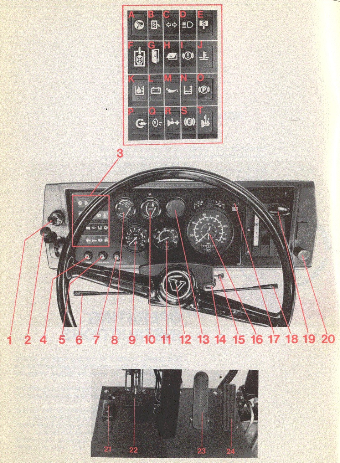
| DASHBOARD AND CONTROLS | |||
|---|---|---|---|
| See page | |||
| 1. | Blocking valve | 4 | |
| 2. | Hand control for parking brake | 8 | |
| 3. | Warning and indicator lights | ||
| A. | Indicator light, retarder, green | 14 | |
| B. | Indicator light, el. heated rearview mirrors, green | 14 | |
| C. | Indicator light, direction indicators, green | 13 | |
| D. | Indicator light, full beams, blue | 13 | |
| E. | Warning light, "STOP" yellow | 14 | |
| F. | Warning light, air temp. engine compartment, red | 14 | |
| G. | Warning light, doors open, red | 15 | |
| H. | Warning light, luggage doors open, red | 15 | |
| I. | Warning light, air pressure, red | 8 | |
| J. | Warning light, coolant temp., engine, yellow | 11 | |
| K. | Warning light, oil level, engine, yellow | 10 | |
| L. | Warning light, charging alternator, yellow | 12 | |
| M. | Warning light, oil pressure, engine, yellow | 10 | |
| N. | Warning light, coolant level, engine, yellow | 11 | |
| O. | Warning light, parking brake, red | 8 | |
| P. | Indicator light, preheating intake air, engine, yellow | 12 | |
| Q. | Warning light, reversing lights, yellow | 15 | |
| R. | Indicator light, torque multiplier, yellow | 16 | |
| S. | Warning light, door brake, red | 15 | |
| T. | Warning light, oil temp. in gearbox, yellow | 16 | |
| 4. | Stop button, engine | 7 | |
| 5. | Cold-start button/preheating button | 12 | |
| 6. | Stalk for direction indicators, full beams, dipped beams switching and headlight flashing | 13 | |
| 7. | "Check" button for warning/indicator lights and buzzer | 19 | |
| 8. | Fuel gauge | 17 | |
| 9. | Air pressure gauge | 8 | |
| 10. | Temperature gauge, coolant, engine | 11 | |
| 11. | Tachometer | 16 | |
| 12. | Horn | - | |
| 13. | Central warning light | 7 | |
| 14. | Radiator blind lever | 11 | |
| 15. | Starter switch | 7 | |
| 16. | Tachograph | 18, 19 | |
| 17. | Switch for instrument lighting | 17 | |
| 18. | Stalk for windscreen wipers and washers | 13 | |
| 19. | Gear shift controls (picture, Allison transmission), see Page 6 for alternative controls | 6 | |
| 20. | Hand throttle control | 17 | |
| 21. | Exhaust brake switch | 9 | |
| 22. | Clutch pedal (only in combination with manual gearbox) | ||
| 23. | Brake pedal | ||
| 24. | Accelerator pedal | ||
There are a number of different types of gear-shift controls depending on the transmission used.
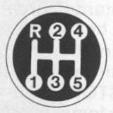 K19
K19For gear-shifting, see page 27.
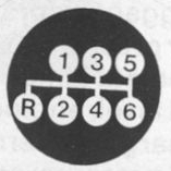 ZF S6-80
For gear-shifting, see page 27.
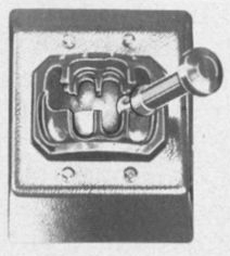 Wilson GB 346/GB 356
For gear-shifting, see page 28.
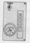 ZF 4 HP 500/5 HP 500
For gear-shifting, see page 31.
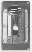 Allison MT 643/644/654 CR
For gear-shifting, see page 34.
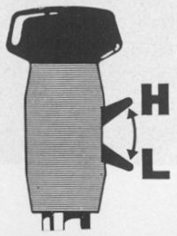 Two-speed final drive
For gear-shifting, see page 38.
TOC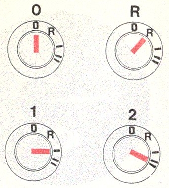 Starter switch (14)
| O | Off (key inserted in this position) |
| R | Radio |
| 1 | Drive |
| 2 | Start. The key must first be pressed in before it can be turned to START. |
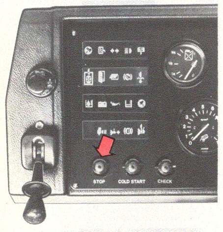 Stop control button (4)
To stop the engine, press the stop button. This stops the injection pump, the fuel injection ceases and the engine stops.
NOTE! The starter key must be at DRIVE in order for the stop control to function. Moreover, there must also be sufficient pressure in the compressed-air system.
See further Page 26.
Do not switch off the main switch until the engine has stopped.
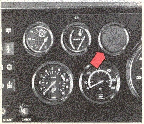
The central warning lights as an extra indicator that one of the warning lights F-T is on. A buzzer also
sounds if the warning lights H, I or J come on.
Never drive the bus if the central light is on.
TOC Air pressure gauge (9)
The air pressure gauge indicates the pressure in the compressed-air reservoir for the front-wheel and drive-wheel circuits. It has two pointers: the white one indicates the pressure for the front-wheel circuit, and the red for the drive-wheel circuit.
The green sector on the gauge notes the working pressure for the compressed-air system.
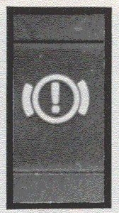 Brake system warning lights (I)
The warning light is connected to both brake circuits. It goes on when the air pressure in any of the brake circuits goes below 4.6-5.2 bars (4.6-5.2 kgf/cm2).
Never start driving as long as this warning light is on.
Should the warning light come on during driving, stop the bus immediately and find out the reason for the drop in pressure.
The new type of symbol is shown in the photo. Older models have a brake pedal as a symbol.
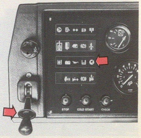 Parking brake warning light (O)
The parking brake operates on the rear wheels. The warning light comes on when the parking brake is applied or if the air pressure in the parking brake circuit is too low for sure release of the parking brake (that is, below 5.1-5.7 bars (5.1-5.7 kgf/cm2). When the hand control is in its forward position with the compressed air system charged and without blocking (see "Blocking Valve, Parking Brake" on Page 9) the parking brake is released.
When the control is moved rearwards, this gradually applies the parking brake which is fully applied when the control is in its rear, latched, position. To release the control from the latched position, lift up the latch sleeve.
TOCNever leave the bus without first ensuring that the parking brake is applied with the control in the latched position.
Never start driving the bus as long as the warning light is on and stop immediately should the light go on during driving.
If a fault should arise in the service brakes during driving, the parking brake can be used as an emergency brake.
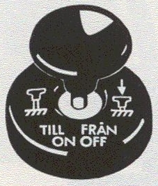 Blocking valve, parking brake (1)
In the event there is no air in the brake system, for example, because the bus has been parked for some time, it will not be possible to release the parking brake until the blocking valve has been pushed in. Even if the hand control for the parking brake is in its forward position, the brakes will not release until the blocking valve has been pressed in, and this can only be done first when the system pressure exceeds 3.4-4.0 bars (3.4-4.0 kgf/cm2).
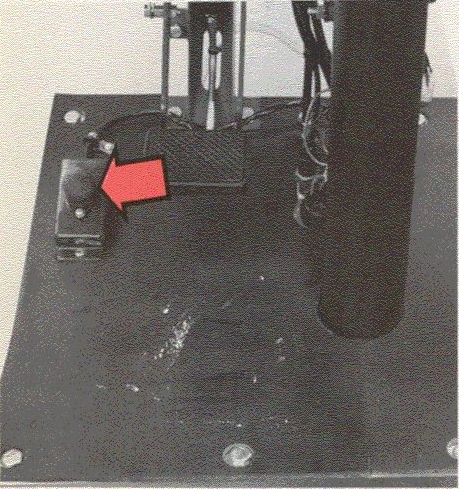 Exhaust brake switch (21)
The exhaust brake is used when necessary as an aid to the footbrake, for example, on downhills. It can also
be used an aid to the footbrake to reduce speed. It is most effective at high engine speed, when the
Tachometer pointer is within the green and upper yellow sectors.
Engine speed must not rise so high that the tachometer pointer enters the red sector. The exhaust brake
functions as long as the switch is depressed.
Operate the exhaust brake daily to prevent parts from sticking.
See also "Exhaust braking during travelling", Page 26.
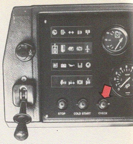 Check button (7)
When the check button is pushed in, all the control/warning lights and the central warninglight should come on and the buzzer sound. This is a check to ensure that all the bulbs and buzzer are functioning. However, it is not a guarantee that all the indicator and warning functions are functioning. Failure at a sender cannot be discovered by depressing the check button.
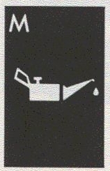 Warning light for engine oil pressure (M)
The warning light goes on when the engine oil pressure goes below 0.5 bar (0.5 kgf/cm2). Should it light during driving, stop the engine immediately and find out the reason for this. It should light when the starter key is at DRIVE but the engine is not running. As soon as the engine starts the light should go out. It can happen that if the engine is warm and at low idle the light goes on without there being any fault. If the engine is already warm, the oil pressure should rise to 3-5 bars (3-5 kgf/cm2).
Consult with a Volvo workshop.
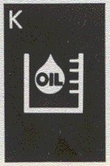 Warning light, engine oil level (K)
This warning light goes on if the oil level in the engine oil tank goes down too far. Stop and check the oil level in the oil tank, see Page 54. Also check for any leakage. When topping up, make sure that the right type of oil is used, see Page 54.
TOC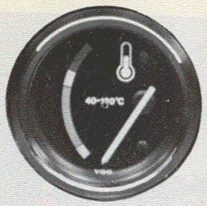 Temperature gauge, engine coolant (10)
The temperature gauge indicates the temperature in the engine cooling system and thereby the engine's working temperature. During driving, the temperature gauge pointer should normally be within the green sector. Under very warm conditions, however, the pointer can be in the upper yellow sector. But the bus should not be driven when the needle is in the red sector.
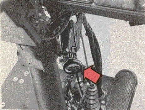 Radiator blind lever (14)
The radiator blind is used to regulate the engine operating temperature with the engine thermostat. You must never drive with the blind down long enough to cause the engine to overheat - this could damage the engine. Do no use the radiator blind during the first 2,500 km (1,500 miles).
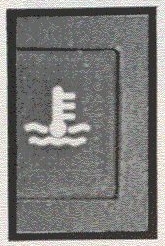 Warning light for engine coolant temperature (J)
Should the coolant temperature light come on during driving, stop the bus immediately but let the engine idle for about one minute before stopping it. Check to see if the temperature gauge is indicating too high a temperature. Also check the Low Coolant warning light (N) for low coolant level. If also this light comes on, probably the reason for the high temperature is too low a coolant level. This can also be checked in the cooling system's expansion tank. Should the coolant temperature be too high, the vehicle's cooling system should be checked at a workshop.
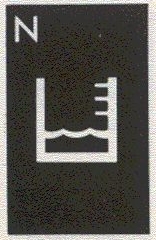 Warning light for low coolant level (N)
Should this light come on during driving, stop and check the level in the cooling system expansion tank. Check the cooling system for leakage before topping-up with coolant. Concerning coolant, see Page 73.
TOC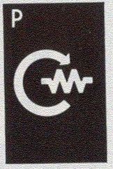 Indicator light, preheating intake-air engine (P)
 To facilitate starting and reduce white smoke after starting, an electric starter heater can be used to
heat the air in the engine's intake manifold. (This is only standard on markets with cold climate). The
starter heater engages automatically for 50 seconds at each start. During the time the heater is engaged.
the light remains on.
To facilitate starting and reduce white smoke after starting, an electric starter heater can be used to
heat the air in the engine's intake manifold. (This is only standard on markets with cold climate). The
starter heater engages automatically for 50 seconds at each start. During the time the heater is engaged.
the light remains on.
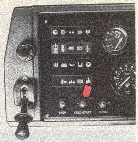
The cold-start/preheating, button is used in cold weather when one wishes to engage the heater coil before starting. See further under "Starting the engine" on Page 24.
The injection pump is fitted with a cold-start device which makes it possible to start the engine under very difficult starting conditions. The device is engaged by operating the combined coldstart/preheating button. See further under "Starting the engine" on Page 24.
On early production, there were separate buttons for cold-start and preheating. See further under "Starting the engine" on Page 24.
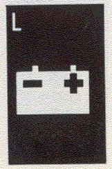 Warning light for battery charging (L)
The lamp comes on when the batteries are discharged. Should the light come on during driving, probably there is a fault in the electrical system or the alternator drive belts are slipping.
The light should come on when the starter key is at DRIVE with the engine switched off.
When the engine starts, the light should go out.
TOCAll the above-mentioned functions are operated by the stalk on the left-hand side under the steering wheel.
Moving the stalk upwards switches on the right-hand direction indicators, moving it downwards switches on the left-hand ones.
Pulling the stalk towards the steering wheel switches on the headlights.
The headlights are flashed even when the headlights are not switched on simply by pulling the stalk towards the steering wheel.
THE SWITCH for the headlights is installed by the coach body builder so that its type and position can vary.
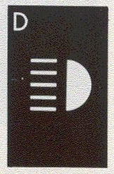 Indicator light for headlights (D)
This light comes on when the headlights are switched on.
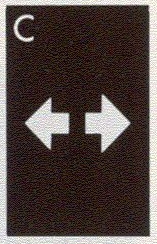 Indicator light for direction indicators (C)
This light starts flashing in unison with the direction indicators.
The windscreen wipers have two speeds. Moving the stalk downwards one step operates the wipers at normal speed, which is recommended for normal driving in rain or snow. Moving the stalk down fully operates the wipers at full speed. This is recommended only when driving in heavy rain or when driving at high speed when it is raining.
The windscreen washer functions when the stalk is moved up towards the steering wheel.
On buses which are equipped with headlamp wipers and washers, these are engaged by moving the stalk
towards the steering wheel. In other words, they are operated in the same way as the windscreen washer,
providing that the main light switch is on.
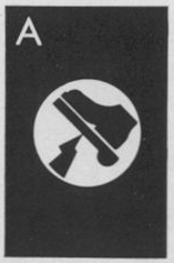 Retarder indicator light (A)
This light goes on when the electric retarder operates. See also Page 39.
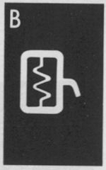 Electrically heated rearview mirrors indicator light (B)
This light goes on when the electrical heating for the rearview mirrors is switched on. The switch is installed by the coach body builder so its location can vary.
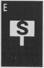 STOP indicator light (E)
This light goes on when a passenger pushes in the alighting button in the bus. It goes out when the bus stops and doors have opened. The function is wired by the coach body builder.
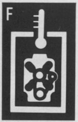 High engine compartment temp. warning light (F)
This light goes on when the air temperature in the engine compartment becomes too high. Should the light go on during driving, stop the bus immediately and find out the reason.
TOC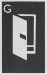 Doors open warning light (G)
This light goes on if any of the doors is open. Driving with open doors is thereby avoided. This function is wired by the coach body builder.
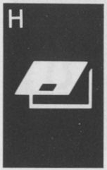 Luggage doors open warning light (H)
This light goes on if a luggage door is open. Driving with open luggage doors is thereby avoided. This function is wired by the coach body builder.
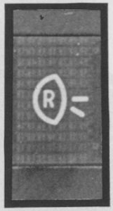 Warning light for reversing lights (Q)
This light goes on when the reversing lights are switched on. The function is wired by the coach body builder.
The new type of symbol is shown in the photograph. Older models have a cab and reversing light as a symbol.
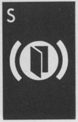 Door brake warning light (S)
To make it impossible to drive with an open door, the bus brakes are operated in certain cases when a door is open. The light goes on when the bus brakes because of the open door. This function is wired by the coach body builder.
TOC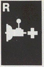 Warning light, torque multiplier (R)
This light goes on if the temperature of the torque multiplier becomes excessive. See also Page 37. (Concerns only buses equipped with Wilson gearbox in combination with torque multiplier).
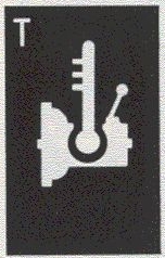 Transmission temperature warning light (T)
This light goes on when the transmission temperature becomes too high. Should it go on during driving, disengage the retarder (Retarder Off). Should it remain on in spite of this, stop the bus and allow the engine to idle with the selector lever in neutral and find out the reason.
For ZF 4 HP 500/5 HP 500 see also Page 33.
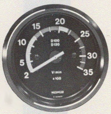 It is important both with regard to fuel economy and the lifespan of the engine that it is allowed to
operate at a correct speed.
It is important both with regard to fuel economy and the lifespan of the engine that it is allowed to
operate at a correct speed.
On buses with the fully automatic transmission (all except the Wilson), the possibility of the driver in influencing the gear-changing points is limited. The tachometer, however, is a valuable check that the gear-changing takes place at the right speed.
TOC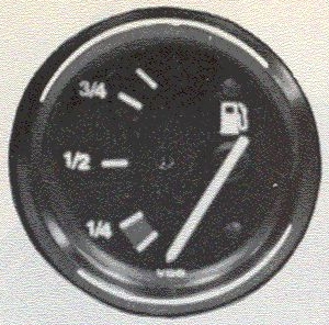 Fuel gauge (8)
The fuel gauge indicates approximately what fuel there is in the tank. When the pointer is at the bottom sector there is approx. 10 % left in the tank.
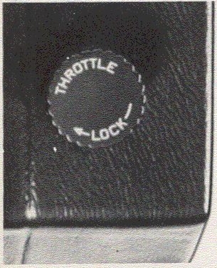 Hand throttle (20)
The hand throttle is used among other things to increase idling speed in order to boost the compressed-air system more rapidly at start.
Do not drive with the hand throttle out! (Increased engine speed increases the temperature and thus wear on the transmission when the bus is stationary.)
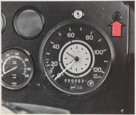 Instrument panel light switch (17)
The instrument panel lighting comes on when the parking lights or the fullbeams dipped beams are switched on. The switch can be used to regulate the panel lighting.
TOC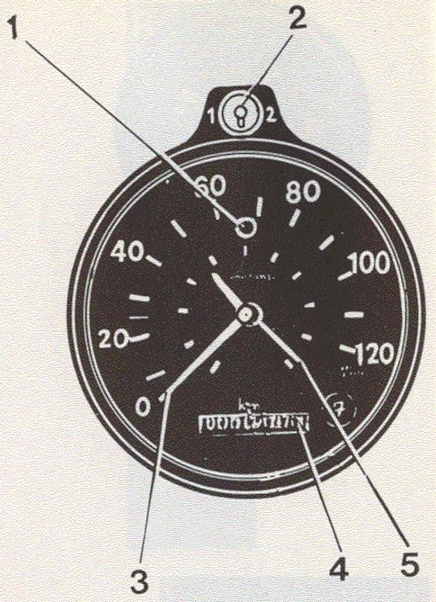
| 1. | Warning lamp |
| 2. | Change-driver lock and switch |
| 3. | Speedometer |
| 4. | Odometer |
| 5. | Clock |
Two different types of tachographs are available depending on the particular market. See Page 19 for the 24-hour type tachograph.
This 7-day type is used for registration during 7 days without having to replace the charts. It registers the speed, total distance driven and time taken. A warning lamp lights when speed increases above 70 km/h. On the charts under the dial the speed, distance driven, driving and stoppage times are registered. The keys supplied and marked 1 and 2 are used switching to the respective chart in connection with change of drivers. The charts should suitably be changed once a week. This is done as follows:
NOTE! The tachograph must not be opened during driving. if it is opened for any other reason than replacing charts, the used (loose) charts must be removed before closing the instrument again. The tachograph must not be used without a chart inside otherwise the stylus will be damaged.
For further information on the tachograph, refer to the instructions of the manufacturer.
TOC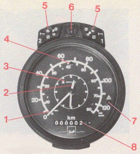
| 1. | Speedometer |
| 2. | Clock |
| 3. | Operating indicator |
| 4. | Speed warning light |
| 5. | Time switches |
| 6. | Lock with key |
| 7. | Function check warning light |
| 8. | Odometer |
There are two different types of tachograph used depending on the market. For the 7-day type, see Page 18. This 24-hour type registers for the driver and second-driver. It registers the speed, total distance driven and time taken. The tachograph has an operating indicator, which tells you whether the instrument is functioning or not, as well as a warning lamp which goes on if the tachograph does not have a chart or if the stylus does not reach the chart. Another warning lamp goes on if a certain speed is exceeded.
Registered on the charts are the speed, distance driven, driving and stoppage times as follows:
 |
effective driving time |
 |
other working time than driving time |
 |
preparatory work, travelling time, waiting time |
 |
rest time |
The tachograph must always have two sets of charts, one for the driver and the other for the second-driver. The top chart and switch 1 is intended for the one at present driving the bus. The chart under and switch 2 is intended for the second-driver. With change of drivers, the charts must also change place in the instrument and the instrument switched to the appropriate symbol.
The tachograph must not be opened during driving and must not be operated without charts otherwise this will damage the stylus. Even if the vehicle does not have a second-driver, there must be two charts in the instrument otherwise the function control lamp will light.
For further information concerning the tachograph, refer to the instructions of the manufacturer.
TOC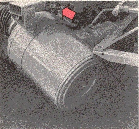 PRESSURE-DROP INDICATOR
The pressure-drop indicator at the air cleaner registers the flow resistance through the air cleaner filter. When the window of the pressure-drop indicator is fully red, the air cleaner insert must be replaced. After the replacement, re-set the pressure-drop indicator by pressing in the button in the bottom of it.
The bus has a main switch, which can switch off the battery current to all functions except the tachograph.
Note that the current must not be broken while the engine is running.
There are two types of main switches: a manual or an electrical. The manual switch is directly wired to the battery cable and is mounted near the batteries. With the electrical main switch the currant is switched off in the actual battery cable with the help of a relay mounted in the battery box. The actual control switch is often smaller and mounted by the coach body builder. Location can vary, but is usually near the front door or the driving seat.
TO AVOID UNINTENTIONAL POWER CONSUMPTION, ALWAYS SWITCH OFF THE MAIN SWITCH WHEN PARKING OR GARAGING THE BUS FOR SOME TIME.
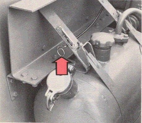 Mechanical stop
In the engine compartment there is a wire control for stopping the engine. Since the function here is mechanical, this wire can function independently of the electrical and compressed-air systems.
TOCThis page left blank.
TOCWhen the bus is new, it should be handled with particular care, especially during the first 5,000 km. Do not take out full output for more than short stretches during this time. Avoid high engine speeds.
Brake smoothly during the first part of the running-in period as the brake drums and brake linings will last longer.
Remember that the oil in the engine, gearbox and rear axle must be changed more often during the running-in. See Page 50.
Turn the starter key to DRIVE.
| 1. | Check that the warning light for low oil level is out. The oil level can also be checked from the oil tank. |
| 2. | Check that the warning light for low coolant level is out. The coolant level can also be checked from the expansion tank. |
| 1. | Check that the parking brake is on. | |
| 2. | Check that the selector lever | |
| is in neutral | (manual gearbox) | |
| is at N | (fully automatic transmission) | |
| is at S | (semi-automatic transmission) | |
| A. | Turn the starter key to the starting position and hold it in this position until the engine starts. |
| A. | Turn the starter key to DRIVE. Push in the cold start button. This switches on the starter heater (preheating) and the indicator light goes on. A timer relay maintains preheating for about 50 seconds. |
| B. | When the light goes out, depress the accelerator pedal 1/3 and turn the starter key to START. See also "Warming a cold engine" on Page 25. The indicator light goes on and the starter heater is engaged for a further 50 seconds post-heating. |
| C. | With low ambient temperature (below -15° C): push in the cold-start button once more in order to engage the cold-start device on the injection pump. (It is not necessary to keep the button pushed in during the entire starting period. Push it in only for a brief moment and then release it.) |
| D. | When the engine has started, the cold-start automatically disengages. |
| E. | With abnormal exhaust smoke, the cold-start button should be pressed in once more after the engine has started in order to get further heating for another 50 seconds. |
| A. | Turn the starter key to DRIVE. Push in the preheating button. This switches on the starter heater (preheating) and the indicator light goes on. A timer relay maintains preheating for about 50 seconds. |
| B. | When the light goes out, depress the accelerator pedal 1/3. |
| C. | With low ambient temperature (below -15° C): push in the cold-start button in order to engage the cold-start device on the injection pump. (It is not necessary to keep the button pushed in during the entire starting period. Push it in only for a brief moment and then release it). |
| D. | Turn the starter key to START. See also "Warming a cold engine" on Page 25. |
| E. | The indicator light goes on and the starter heater is engaged for a further 50 seconds. When the engine has started, the cold-start automatically disengages. |
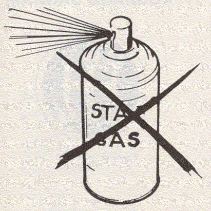
Never race a cold engine. The lubricating oil is then cold and sluggish so that it takes time to penetrate to all the engine's lubricating points so there is a risk of serious damage to the engine if raced. Because of its design the THD 100-engine has a separate oil tank with longer hoses than in a conventional engine. This means that special care must be observed.
Note that this also applies even if the bus was connected to a so-called "ramp heater" since the oil in the separate oil tank is sluggish.
Do not let engine speed exceed 11-12 r/s (600-700 r/min) until after a minute or two.
Increase the engine speed gradually, before driving the bus, until normal operating speed is attained. Check at the same time the oil pressure warning light. If the light goes on, reduce engine speed immediately to idle speed and repeat warm-up procedure.
Never load the engine unless it has reached its normal operating temperature.
TOC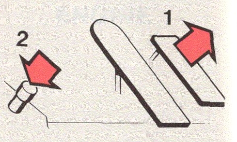
| 1. | Release the accelerator pedal. |
| 2. | Depress the foot switch. |
| 3. | Exhaust braking stops when you release the foot switch. |
NOTE!
The injection pump does not disengage automatically with exhaust braking. It is therefore important that
you release the accelerator pedal before you depress the foot switch in order to avoid damage to the valve
system or heavy exhaust smoke.
The engine is stopped by pushing in the stop button on the dashboard. it can also be stopped by pulling out the mechanical stop control in the bus engine compartment. After the bus has been driven hard, the engine should be allowed to idle for a minute or two before it is stopped in order to smooth out heat stresses.
Do not forget to switch off with the starter key.
TOCWhen changing to a higher gear, you should always keep the gear lever steady for a moment in neutral before engaging the higher gear.
When changing down, it is suitable to keep the foot on the accelerator, provided that you move the gear lever fairly quickly. This will give the engine an opportunity to increase to a suitable speed corresponding to the higher reduction ratio.
Gear-lever positions K 19 gearbox
The K 19 gearbox is a 5-speed unit, with the four highest speeds synchronized. The different gear positions can be seen from the adjacent illustration.
Gear-lever positions ZF S6-80 gearbox
The ZF S6-80 type gearbox is a six-speed, fully synchronised gearbox. The gear lever positions are shown on the adjacent picture.
TOC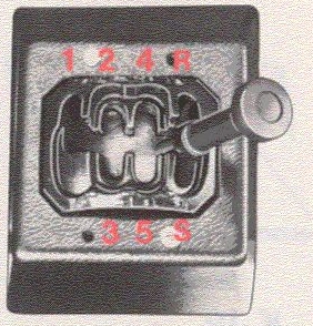
5-Speed
| Gear position, Wilson |
|---|
| R = Reverse |
| S = Start |
4-Speed
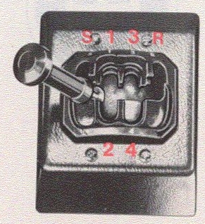
A bus fitted with the WILSON semi-automatic transmission does not have a clutch pedal. Gear-changing is via the selector lever which is moved to the desired position and the gear engages electro-pneumatically.
The transmission may be 4-speed or 5-speed. The selector lever for the Wilson semi-automatic is provided with a reverse inhibitor which must be moved up the selector lever before reverse can be engaged.
The selector lever has also a down-change inhibitor which means that you must change gear via 4th (3rd on 4-speed) when changing down from 5th (4th on 4-speed) to the lower gears. S is the start position.
| 1. | When the centre indicator light goes out, the bus is ready for driving away. |
| 2. | Depress the footbrake pedal and release the parking brake. (When the parking brake is on, there is no current to the selector lever so that a gear cannot be engaged until the parking brake is released.) |
| 3. | Move the selector lever to one. The engine should then idle. |
| 4. | Release the footbrake pedal and let the bus roll out under light throttle. |
| 1. | Move the selector lever to neutral, lightly depress the accelerator pedal, wait a moment and then move the selector lever to the nearest higher gear position. |
| 1. | Move the selector lever to neutral, increase throttle (adapt it to speed) and then move the lever to the nearest lower gear position. |
NOTE! Never let the bus roll with the selector lever at neutral. This could damage the planetary gearing because of lack of oil.
TOC| 1. | Brake with the footbrake to stop the bus. |
| 2. | Move the selector lever to neutral. Hold the bus stationary with the footbrake or if necessary with the parking brake. (If the selector lever is not moved to neutral, this can overheat and damage the hydraulic clutch.) |
| 3. | When ready to drive away, move the selector lever to one with the engine idling. |
| 4. | Release the brake and allow the bus to drive away smoothly under light throttle. |
NOTE! Never leave the driving seat without having the selector lever in neutral and the parking brake on.
| 1. | Stop the bus with the footbrake and engage the parking brake. |
| 2. | Move the selector lever to neutral. |
| 3. | Stop the engine with the stop button on the dashboard. |
| 4. | Turn the starter key to the garage position. |
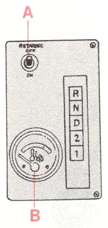
A = Engaging and disengaging the retarder
B = Fluid temperature guage
These are 4-stage and 5-stage automatic transmissions with torque converter/retarder.
| R | Reverse |
| N | Neutral. Pushing in button N re-sets all the other buttons to their initial position. When changing between forward and reverse, first depress button N. |
| D | Normal position for driving forwards. Automatic changing-up and down between 1st, 2nd, 3rd and 4th (and 5th on 5-stage transmission). |
| 2 | Automatic changing-up and down between 1st, 2nd and 3rd (and 4th on 5-stage transmission). |
| 1 | 1st gear is engaged. No change-up. |
The engine can only be started when button N is pushed in.
Select the desired gear position by pushing in one of the buttons (bus stationary, engine idling). Release the parking brake and drive off smoothly under light accelerator pedal pressure.
TOCPosition D for the selector lever is used when driving under normal traffic conditions. Position 2 is used if the bus is carrying a heavy load or the traffic is so dense that you do not wish to change-up (e.g. if there is too frequent changing-up and down because of the traffic, etc., select the nearest lower gear by depressing button 2 or 1). Position 1 is suitably used when garaging the bus or moving it a short distance. All the forward gears can be selected for driving forwards. If button 2 or 1 is depressed when the bus is travelling at a speed higher than that corresponding to the particular gear position, change-down takes place first only when the engine's maximum speed is not exceeded.
Reverse is engaged by pushing in button R.
Changing gear from forward to reverse can only be done after button N is first depressed.
The full throttle position for the accelerator pedal is felt by resistance from the pedal. If changing down gear is required, for example when overtaking, depress the accelerator pedal to the floor past this pressure point (kick-down).
TOCFor brief stops, pushbuttons D, 2 or 1 must remain depressed: the bus is held stationary only with the footbrake or the parking brake. The N-button is depressed only when the driver leaves his seat for a moment or when the engine has stopped.
Since there is no parking position, always remember to use the parking brake.
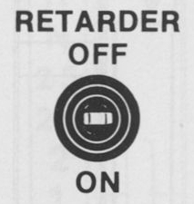 The transmission brake/retarder is operated by means of the brake pedal. When the brake pedal is depressed,
the retarder is uniformly operated during the first stage of pedal travel. Further pressure on the brake pedal
results in full-braking using the retarder and at the same time the compressed-air brakes start to operate.
With a slippery road surface, the retarder should be disengaged since it operates only on the rear wheels.
This is done electrically by operating the button marked "RETARDER ON/OFF", on the bus's gear selector panel.
The transmission brake/retarder is operated by means of the brake pedal. When the brake pedal is depressed,
the retarder is uniformly operated during the first stage of pedal travel. Further pressure on the brake pedal
results in full-braking using the retarder and at the same time the compressed-air brakes start to operate.
With a slippery road surface, the retarder should be disengaged since it operates only on the rear wheels.
This is done electrically by operating the button marked "RETARDER ON/OFF", on the bus's gear selector panel.
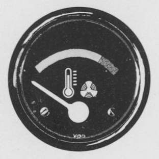
| Green sector | - | Normal transmission temperature |
| Red sector | - | Excessive fluid temperature warning lamp for transmission temp. lights |
Should the temperature become too high, speed must be reduced or the retarder disengaged. Should this not reduce the temperature, the bus must be stopped. Engage neutral, depress the accelerator pedal to the floor and keep it there for several seconds. If the temperature does not drop immediately, this may be due to the oil level being too low or there is a fault in the transmission oil cooling.
TOC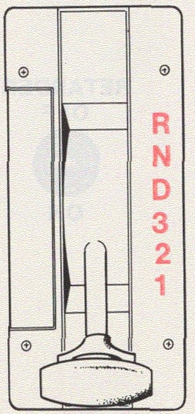 MT 643/644
These transmissions are 4-step or 5-step automatic units with torque converter.
The transmission is operated by a selector lever situated on the right-hand side of the instrument panel.
NOTE! The bus must be stationary when you move the selector lever from a forward gear to R or from R to a forward gear.
Use this position when starting the engine and for longer stops with the engine running. The engine cannot be started with the selector lever in any other position.
Always apply the parking brake when the bus is stationary with the selector lever at N.
Never let the bus roll with the selector lever at N as this could damage the transmission.
The bus starts in 1st. As it increases speed. there is automatic change-up into 2nd, 3rd and 4th. When the bus is braked, there is automatic change-down to the appropriate gear.
For brief stops, the selector lever should not be moved to neutral.
These positions are used, e.g. if the bus is heavily loaded or the traffic so dense that you do not wish to change to a higher gear.
Use this position only when moving the bus a short distance and when garaging it.
TOC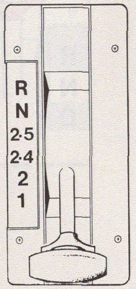 MT 654
NOTE! The bus must be stationary when you move the selector lever from a forward gear to R or from R to a forward gear.
Use this position when starting the engine and for longer stops with the engine running. The engine cannot be started with the selector lever in any other position.
Always apply the parking brake when the bus is stationary with the selector lever at N.
Never let the bus roll with the selector lever at N as this could damage the transmission.
The bus starts on 2nd gear and, as speed increases, there is automatic change-up into 3rd, 4th and 5th.
There is automatic down-change when the bus speed decreases.
For brief stops, the selector lever should not be moved to neutral.
Use positions 2-4 or 2, e.g., if it is not desirable to change up because of the bus load or traffic situation. Position 2 gives the best engine braking effect.
This gear can only be engaged by moving the selector lever to position 1. This creep speed is more than twice as powerful as the low-speed (2).
Use this position for very slow driving under difficult conditions or when starting on a steep uphill with a heavily loaded bus.
TOC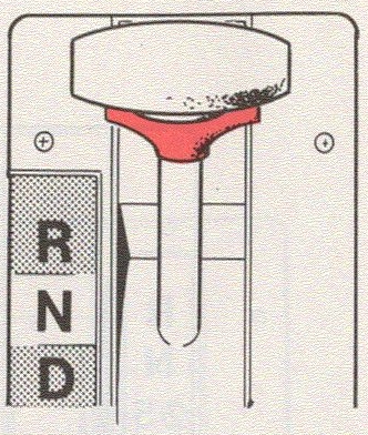 Selector lever inhibitor
The selector lever is provided with an inhibitor to prevent un-intentionally engaging the "wrong" gear.
The inhibitor must be pressed in when gear-changing.
The inhibitor, on the other hand, does not need to be pressed in when moving the selector lever to a "higher" gear position or when moving it from D to N.
The engine can only be started when the selector lever is at N.
To drive away, press in the inhibitor, move the selector lever to the desired driving position and depress the accelerator pedal.
The speed at which the transmission changes-up to the next higher gear will depend on how much you depress the accelerator pedal. With the accelerator pedal depressed to the floor, there is change-up at high speed, near the engine's max. speed. With the accelerator pedal lightly depressed, there is change-up at a lower speed.
If the selector lever is at any of the low-gear positions, there is no change-up to the highest gear (unless the engine is overrevved).
For brief stops, the selector lever should not be moved to neutral; the bus should be held stationary with the footbrake or the parking brake. Only when the driver leaves the driving seat for a moment or when the engine has stopped should the selector lever be moved to N. Since the transmission has no parking position, the bus must always be parked by using the parking brake.
TOCThe four-speed Wilson type automatic transmission can be equipped with a torque multiplier which increases the starting-off power on each gear. You start and gear-change the bus in the usual way when driving with a Wilson transmission.
The torque multiplier engages and disengages automatically depending on the speed of the engine. If you drive at high speed on a motorway (engine speed above approx. 29 r/s (1,750 r/min), the torque multiplier disengages in order to avoid energy losses caused by the multiplier. It engages automatically again when the speed drops to below 25 r/s (1,500 r/min). A warning light goes on when the temperature of the torque multiplier becomes excessive, see Page 16.
Should the light go on during driving, change down a gear and allow the engine to run at a higher speed or move the gear lever to neutral and allow the engine to run at about 17 r/s (1,000 r/min) until light goes out.
TOC
| H | = High |
| L | = Low |
For those buses equipped with a two-speed final drive, gear-changing takes place in the ordinary way. High or low gear is engaged electrically by means of the switch.
For the manual transmission - the switch is on the gear lever.
For the semi-automatic transmission - the switch is on the dashboard.
The two-speed final drive doubles the number of gears.
Those in the low-speed range provide large pulling power and those in the high-speed range high speed.
Gear-changing is carried out by means of an electric motor.
| 1 | Depress accelerator pedal fully. |
| 2 | Move switch up to HIGH. |
| 3 | Wait a couple of seconds to enable the electric motor to prepare for the change-up. |
| 4 | Release the accelerator pedal and allow the bus to roll until you feel gear-changing has taken place. |
| 1 | Depress the accelerator pedal fully. |
| 2 | Move the switch down to LOW. |
| 3 | Wait a couple of seconds to enable the electric motor to prepare for the change-down. |
| 4 | Quickly ease up on the accelerator pedal and then immediately depress it until change-down takes place. |
NOTE! Do not use the exhaust brake when changing from low to high or vice-versa. To do so might run the risk of the final drive being in a non-engaged position and the engine stops so that the steering looses its power-assistance.
The low speed in the final drive should primarily be used in order to spare the gearbox and final drive. Use, for example, preferably second gear and the low-speed range rather than first gear and the high-speed range.
TOCAs optional equipment, the bus can be fitted with an electric retarder, a form of brake which is fitted on the propeller shaft and is engaged as soon as you depress the brake pedal, providing that the bus is driven at a speed exceeding 3 km/hour (2 mile/hour). To get the best out of the electric retarder. which will provide you with smooth braking, you should not depress the brake pedal during normal braking longer than just to engage the retarder. Normally the retarder can cope with braking the bus. At 3 km/hour (2 mile/hour) the retarder disengages automatically and then you must depress the brake pedal again in order to get the normal compressed-air brakes to function and to stop the bus entirely.
A warning light (refer to Indicator Light A. on Page 5) goes on when this brake is engaged. It should be out when the bus is standing still. If it does not go out then, this indicates some fault in the regulator, a fault which could quite well discharge the battery rapidly.
If the bus is standing still and you depress the brake pedal, the electric retarder engages for a very brief moment. The warning light blinks for a brief moment.
Where the road surface is slippery, you should remember that the electric retarder engages as soon as you touch the brake pedal and also that you can use it to prevent the wheels from locking.
NOTE that the electric retarder cannot be used as a parking brake.
TOC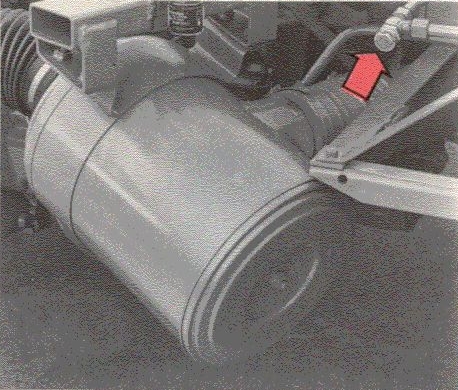
Check valve, engine compartment
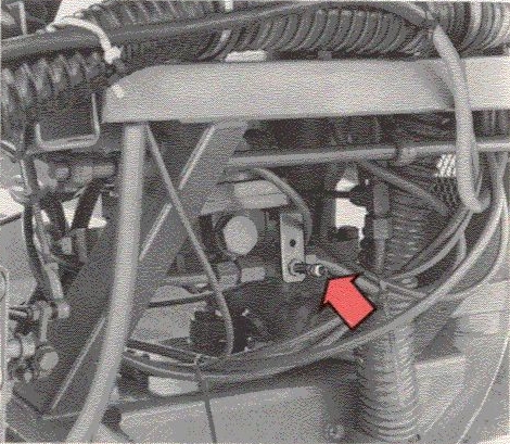
Connection, pump valve
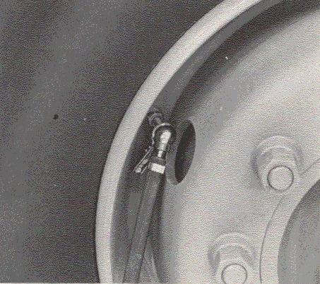
Connection wheel
Note! When towing further than 200 metres, the rear axle drive shafts or the propeller shaft must be removed.
Note that the engine cannot be started by towing if the bus is equipped with automatic transmission.
When the bus is to be moved or towed and the engine cannot be started to enable the compressor to boost up the compressed-air system, the drive wheel brake cylinders must be filled with air so that the parking brake can be released.
If there is access to compressed air, the compressed-air system can be filled via the check valve in the engine compartment. The bus air pressure gauge should register the pressure in this case. If there is no access to compressed air, the parking brake can be released in the following way:
| Note! Someone should be behind the steering wheel when releasing the parking brake in the event the bus should start to roll. |
This fills the lines to the lower side of the drive wheel cylinders with air and the parking brake releases providing that the pressure in the tyre exceeds approx. 5 bars (500 kPa) (fully released at 5.8-6.6 bars/580-660 kPa). The bus air pressure gauge will not give a reading but filling can be discontinued as soon as the air flow has stopped.
The bus can then be towed. Note, however, that the towing must be done with a rigid tow bar or similar since the bus footbrake does not work when only the parking brake cylinders are filled. In cases of emergency, braking can of course be carried out by moving the manual control for the parking brake to the rear position, but compressed air must be supplied again in order to release the parking brake.
TOCWhen towing lengthy distances, check to make sure that the parking brake is not on because of air leakage.
Also note that the power-assisted steering does not function during towing, so extra force must be used to turn the steering wheel in order to steer the vehicle.
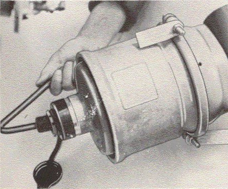
In cases of emergency, the parking brake can also be released mechanically if there is no compressed air available.
This is done as follows:
| Always start by chocking the wheels to prevent the bus from rolling. This is most important since you must crawl under the bus to do the following work. |
Remove the plastic cap on the rear side of the cylinder. The bolt which is now visible can be unscrewed with the appropriate spanner from the tool kit until the brake releases.
Remember to re-screw the bolt to its original position after the towing and re-fit the plastic cap.
TOCIf necessary the tyres can be inflated with air supplied by the vehicle's compressed-air system. This is done as follows:
NOTE! It is not necessary to release the parking brake.
| 1 | Connect the clamp head of the tyre inflation hose supplied to the valve on the tyre to be inflated. |
| 2 | Connect the other end of the hose to the pump valve under the footbrake valve. |
| 3 | If necessary, start the engine so that the compressor boosts the compressed-air system. The highest pressure which the tyre can thereby be inflated is the same as the highest working pressure, that is, 7.3-8.0 bars (730-800 kPa). |
| 4 | Check to make sure that the blocking valve is pushed in. |
All that is really needed for the power-assisted steering to function perfectly is that the instructions concerning the oil and lubrication are followed.
Should the front wheels, however, be blocked sideways, e.g., against a curb, there is absolutely no point in trying to get the wheels away from the curb by forcing with the steering wheel. Excessive force on the steering wheel opens the guide valves and this causes the oil pressure to rise. If the oil pressure rises to max. 50-100 `bars (5-10 MPa), the oil temperature in the power-assisted steering gear will also rise with consequent risk of the oil pump overheating. An overheated oil pump can seize. If the hydraulic system should not function, nor the power-assisted steering, it will feel as if the steering gear has locked itself. This is not the case, however, you can steer the bus but more effort must be used in doing so.
TOC| 1 | Check after starting and now again when driving that the instruments are functioning normally. Should any light go on while driving, stop and find out the reason. |
| 2 | Never race a cold engine. |
| 3 | The engine should be idling when you engage a gear when about to drive the bus. |
| 4 | Disconnect the propeller shaft if the bus is to be towed. |
| 5 | Do not try to start a bus equipped with automatic transmission by towing. This would damage the transmission. |
| 6 | Never block the radiator. The cooling system thermostats maintain the right temperature at all times. Check the coolant regularly and use the proper type when, e.g., filling up. Fill with coolant with the engine warm and switched off. |
| 7 | Change the coolant filter according to the maintenance scheme and when changing the coolant. Check the cooling system hoses regularly. Do not drive with a leaking cooling system. |
| 8 | Do not drive until the pointer on the air pressure gauge enters the green sector on the gauge. |
| 9 | Allow the engine to idle for about a minute or two after severe driving before stopping it in order to avoid heat stresses in the engine and coolant losses. |
| 10 | Use the exhaust brake (with right gear engaged) on downhills and during lengthy braking. Operate the exhaust brake daily to prevent its parts from sticking. |
| Top | Next |