This document is under construction.
Back to the Volvo B58 Operator's Manual index page
| MAINTENANCE | Page | |
|---|---|---|
| General | 44 | |
| System-Service | 45 | |
| Maintenance scheme | 46 | |
| Lubrication during running-in | 50 | |
| Daily inspection | 52 | |
| Wintertime | 53 | |
| Lubrication, oils, oil changes | ||
| engine | 54 | |
| manual transmission | 56 | |
| gear lever carrier | 59 | |
| hydraulic clutch | 60 | |
| torque multiplier | 61 | |
| semi-automatic transmission | 62 | |
| automatic transmission | 64 | |
| final drive | 68 | |
| steering | 70 | |
| all-round lubrication | 71 | |
| Cooling system | 72 | |
| Fuel system | 76 | |
| Electrical system | 78 | |
| Brake system | 82 | |
| Tyres and wheels | 84 | |
A warranty booklet is supplied with the bus and contains coupons covering warranty service. If possible allow the dealer who supplied the bus to carry out this servicing. If this is not possible, you can go to another authorized Volvo workshop. If our warranty is to apply, the above-mentioned warranty services must be carried out at about the mileage stipulated and the bus must be maintained in accordance with the instructions given in this manual.
To ensure that your bus gets perfect maintenance also in the future, you should reach some kind of agreement with your Volvo workshop about continued service.
TOCIf the bus is to retain its original properties throughout its entire lifetime, regular maintenance is required, in other words - SYSTEM-SERVICE.
You are urged to get in touch with your local Volvo workshop and with their help draw up a servicing program in accordance with the Volvo SYSTEM-SERVICE for buses. The Volvo workshop is the most suitable workshop to look after your bus because it has:
The Volvo SYSTEM-SERVICE for buses consists of 4 different service programs: B1 at 5,000 km, B2 at 10,000 km, B3 at 40,000 km and B4 at 80,000 km.
TOC| Measures | To be carried out after every (km) |
See Page |
|
|---|---|---|---|
| Oils, oil checks, oil changes, oil filters | |||
| 1 | Engine oil, check | Daily | 54 |
| 2 | Engine oil, change1 | 10,000 | 55 |
| 3 | Engine oil filter, change1 | 10,000 | 55 |
| 4 | Manual transmission, check oil | 5,000 | 56, 58 |
| 5 | Manual transmission, change oil7 | 40,0003 | 57, 59 |
| 6 | Gear lever carrier, check oil | 5,000 | 59 |
| 7 | Gear lever carrier, change oil5 | 80,000 | 59 |
| 8 | Hydraulic clutch, check oil | 5,000 | 60 |
| 9 | Hydraulic clutch, change oil5 | 40,000 | 60 |
| 10 | Torque multiplier, check oil | Daily | 61 |
| 11 | Torque multiplier, change oil | 10,000 | 61 |
| 12 | Wilson semi-automatic transmission, check oil | 5,000 | 62 |
| 13 | Wilson semi-automatic transmission, change oil and clean oil filter2 | 20,000 | 63 |
| 14 | ZF automatic transmission, check oil | 5,000 | 64 |
| 15 | ZF automatic transmission, change oil and filter2 | 30,000 | 65 |
| 16 | Allison automatic transmission, check oil | 5,000 | 66 |
| 17 | Allison automatic transmission, change oil and clean filter4 | 40,000 | 67 |
| 18 | Final drive check oil | 5,000 | 68 |
| 19 | Final drive, change oil4 | 40,000 | 68 |
| 20 | Two-speed final drive, check oil | 10,000 | 69 |
| 21 | Power-assisted steering, check oil | 5,000 | 70 |
| 22 | Power-assisted steering, change filter4 | 80,000 | 70 |
| 23 | Angled gear, steering gear, check oil | 5,000 | 70 |
| 24 | Clutch fluid reservoir, check level | 5,000 | 71 |
| 25 | Fan drive, check oil | 5,000 | 71 |
| 26 | Fan drive, change filter8 | 40,000 | 71 |
| 27 | Chassis, all-round lubrication | 5,000 | 71 |
| Further measures which can be carried out by driver or owner | |||
| 28 | Coolant, check level | Daily | 72 |
| 29 | Coolant, change | Every autumn | 73 |
| 30 | Coolant filter, change | 20,000 | 75 |
| 31 | Battery, check acid level | 5,000 | 79 |
| 32 | Brake system, check pressure regulator and warning lamps | Daily | 82 |
| 33 | Brake system, check for leakage | 10,000 | 82 |
| 34 | Brake system, check filter in air dryer | Once a year | 83 |
| 35 | Brake system, anti-freeze container, top up fluid | See page | 83 |
| 36 | Tyre pressure, check | Each week | 84 |
| 1) | The oil in the engine should be changed at least twice a year. With a new or newly overhauled engine,
the first oil change should take place with the 2,500km warranty service, the second after 5,000km and the
third in connection with the 10,000km warranty service. With a new or newly overhauled engine, change the oil filter at the 2,500km and 10,000km warranty services. |
| 2) | However, carried out at least once a year. During the running-in also in connection with the 2,500km warranty service. |
| 3) | For buses in City or suburban traffic and equipped with K19 type gearbox, the oil should be changed every 20,000km. |
| 4) | However, carried out at least once a year. During the running-in also in connection with the 10,000km warranty service. |
| 5) | However, carried out at least once a year. |
| 6) | However, carried out at least once a year. During the running-in also in connection with the 10,000km warranty service, on which occasion the oil is also changed. |
| 7) | However, carried out at least once a year. During the running-in also after 10,000km. |
| 8) | During the running-in also after 2,500km. Change the oil every 80,000km. |
|
|
|
|
|
||||||||||||||||||||||||||||||||||||||||||||||||||||||||||||||||||||||||||||||||||||||||||||||||||||||||||||||||||||||||||||||||||||||||||||||||||||||||||||||||||||||||||||||||||||||||||||||||||||||||||||||||||||||||||||||||||||||||||||||||||||||||||||||||||||||||||||||||||||||||||||||||||||||||||||||||||||||||||||||||||||||||||||||||||||||||||||||||||||||||||||||||||||||||||||||||||||||||||||||||||||||||||||||||||||||||||||||||||||||||||||||||||||||||||||||||||||||||
|
||||||||||||||||||||||||||||||||||||||||||||||||||||||||||||||||||||||||||||||||||||||||||||||||||||||||||||||||||||||||||||||||||||||||||||||||||||||||||||||||||||||||||||||||||||||||||||||||||||||||||||||||||||||||||||||||||||||||||||||||||||||||||||||||||||||||||||||||||||||||||||||||||||||||||||||||||||||||||||||||||||||||||||||||||||||||||||||||||||||||||||||||||||||||||||||||||||||||||||||||||||||||||||||||||||||||||||||||||||||||||||||||||||||||||||||||||||||||||||
|
||||||||||||||||||||||||||||||||||||||||||||||||||||||||||||||||||||||||||||||||||||||||||||||||||||||||||||||||||||||||||||||||||||||||||||||||||||||||||||||||||||||||||||||||||||||||||||||||||||||||||||||||||||||||||||||||||||||||||||||||||||||||||||||||||||||||||||||||||||||||||||||||||||||||||||||||||||||||||||||||||||||||||||||||||||||||||||||||||||||||||||||||||||||||||||||||||||||||||||||||||||||||||||||||||||||||||||||||||||||||||||||||||||||||||||||||||||||||||||
|
||||||||||||||||||||||||||||||||||||||||||||||||||||||||||||||||||||||||||||||||||||||||||||||||||||||||||||||||||||||||||||||||||||||||||||||||||||||||||||||||||||||||||||||||||||||||||||||||||||||||||||||||||||||||||||||||||||||||||||||||||||||||||||||||||||||||||||||||||||||||||||||||||||||||||||||||||||||||||||||||||||||||||||||||||||||||||||||||||||||||||||||||||||||||||||||||||||||||||||||||||||||||||||||||||||||||||||||||||||||||||||||||||||||||||||||||||||||||||||||||||||||||||||||||||||||||||||||||||||||||||||||||||||||||||||
|
||||||||||||||||||||||||||||||||||||||||||||||||||||||||||||||||||||||||||||||||||||||||||||||||||||||||||||||||||||||||||||||||||||||||||||||||||||||||||||||||||||||||||||||||||||||||||||||||||||||||||||||||||||||||||||||||||||||||||||||||||||||||||||||||||||||||||||||||||||||||||||||||||||||||||||||||||||||||||||||||||||||||||||||||||||||||||||||||||||||||||||||||||||||||||||||||||||||||||||||||||||||||||||||||||||||||||||||||||||||||||||||||||||||||||||||||||||||||||||||||||||||||||||||||||||||||||||||||||||||||||||||||||||||||||||
During the running-in period, the moving parts of the bus must be trimmed in order to get smooth and strong sliding surfaces. For this reason oil changing should be carried out more frequently during the running-in period than is normal later on.
| First oil change: | 2,500 Km |
| Second oil change: | 5,000 km |
| Third oil change: | 10,000 km |
Thereafter according to the maintenance scheme.
| First change: | 2,500 Km |
| Second change: | 5,000 km |
Thereafter every 10,000 km.
First oil change after 10,000 km. Thereafter according to the maintenance scheme.
First change of filter after 2,500 km. Thereafter according to the maintenance scheme.
First oil change and cleaning of oil filter after 2,500 km. Thereafter according to the maintenance scheme.
First oil change and changing of filter in connection with the 2,500 km warranty service. Thereafter according to the maintenance scheme.
First oil change and replacement of filter after 10,000 km. Thereafter according to the maintenance scheme.
TOCFirst oil change after 10,000 km, at which the final drive is flushed clean. Second oil change after 40,000 km. Thereafter every 40,000 km (or at least once a year).
First oil and filter change after 10,000 km. Thereafter according to the maintenance scheme.
With the all-round lubrication at 5,000 km, the oil in the engine, transmission, final drive and power-assisted steering and also check the fluid levels in the batteries, cooling system and washer reservoirs should also be checked
TOC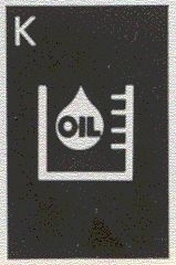

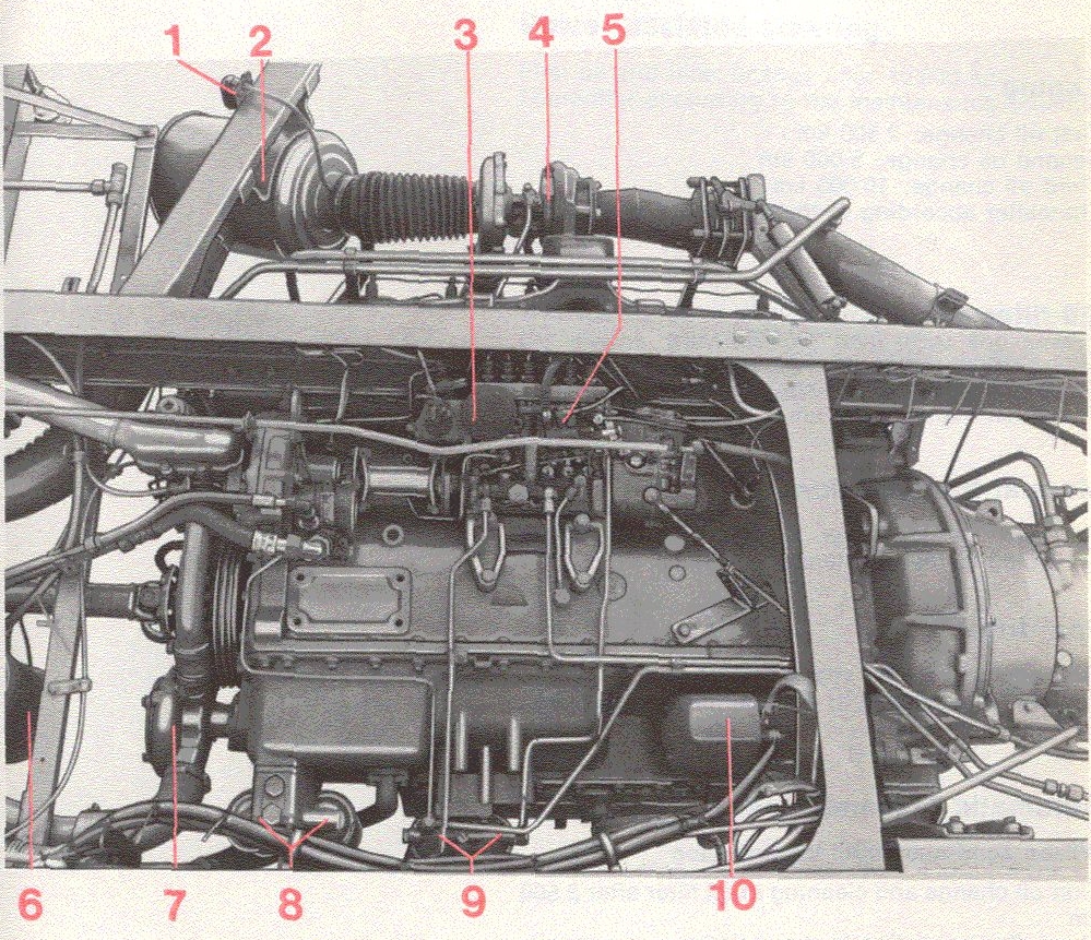
| 1. | Engine oil. Before starting the engine check that the warning lamp for low Oil level is out (starter key at DRIVE). If it is necessary to top-up with oil, use the same quality already used in the engine. | |
| 2. | Coolant. Before starting the engine check that the warning lamp for low coolant level is out (starter key at DRIVE). If topping-up is necessary, fill with water + glycol (use Volvo glycol). | |
| 3. | Brake system pressure regulator and warning lamp. | |
| A. | Start the engine. The indicator light should turn on and go out again when pressure has reached 4.6-5.2 bars (4.6-5.2 kgf/cm2). | |
| B. | Check with the air pressure gauge that the pressure regulator disengages when pressure reaches 7.3-8.0 bars (7.3-8.0 kgf/cm2). | |
| C. | Depress and release the brake pedal and check that the compressor re-engages when pressure has dropped to 6.3-7.0 bars (6.3-7.0 kgf/cm2). | |
| 4. | Horn, direction indicators, windscreen wipers and washers, rearview mirrors, brake lights and all the other lighting. | |
To avoid any unnecessary trouble which may arise during the wintertime, you should have your bus checked in good time.
At low temperatures, it is important that you use oils with the correct viscosity in the engine, transmission and final drive, see the recommendations on pages 54-73 or in the lubrication chart at the end of this book.
If freezing weather is anticipated, make sure that the cooling system is protected by using at least 40% glycol in the coolant. Keep the winter mixture for the entire year and top up when necessary with water + glycol, in order to maintain good protection against rusting. Use Volvo's glycol.
Use the winter fuels supplied by the oil companies. Always try to keep the tank as well-filled as possible. Do not put methylated spirits in the fuel tank. You should try to fill the tank immediately after completing driving for the day.
During the wintertime the batteries are exposed to considerably more stresses than during the summertime, since lighting, etc, is used more often. Also the capacity of the batteries drop as the temperature drops. Check the batteries regularly - poorly charged batteries can be damaged by frost.
TOCAlways make sure that the engine gets oil of a well-known make. It must be able to meet the following quality requirements:
| Oil quality | Viscosity1 | ||
| Below -10°C2 | -10°C to +20°C | Above +20°C | |
| For Service CD (MIL-L-2104 C) | SAE 15 W/40* | ||
| SAE 10 W or SAE 10 W/20 or SAE 10 W/30 | SAE 20 W/20 | SAE 30 | |
| or SAE 20 W 30 | |||
| 1) | The temperatures refer to stable ambient temperatures. |
| 2) | Or when cold-start difficulties can be expected. |
| *) | Note! At temperatures below -20°C, SAE 10 W or SAE 10 W/20 should be used instead of SAE 15 W-40. |
Check the engine oil level daily in connection with starting the engine.
Check the oil level with the warning lamp for low oil level.
The oil level can also be checked with the dipstick in the oil tank. The level should be between the marks on the dipstick. Under no circumstances is it permitted to go below the lower mark.
Note! On certain markets the oil tank has a sight glass instead of a dipstick.
If you have to top-up with oil, use the same type already in the engine.
For buses with torque multiplier, see also page 6161.
TOC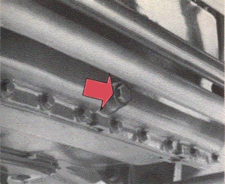
Dry sump
Inspection cover
Oil reservoir
The engine oil should be changed every 10,000 km, or at least every 6 months.
(Also during the running-in:
| 1st time at | 2,500 Km |
| 2nd time after | 5,000 km |
| 3rd time at the warranty service after | 10,000 km) |
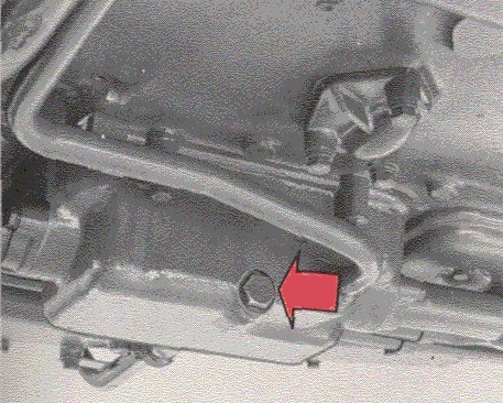
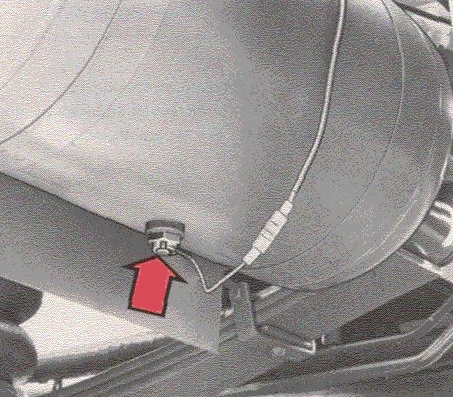
The three plugs on the engine must first be removed in order to drain the oil. One is at the lower edge of the dry sump, the other at the oil pocket on the inspection panel and the third underneath the oil tank.
| Oil capacity incl. oil filter: | 25 litres. |
| Oil capacity incl. torque multiplier: | 43 litres. |
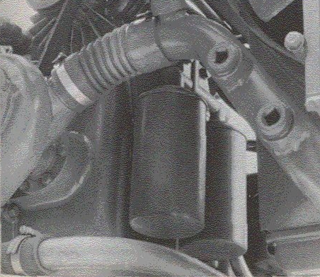
The engine has two lubricating oil filters. These can be replaced every 10,000 km when changing the oil. (During the running-in, the filters must also be changed at the 2,500 km and 10,000 km warranty services.)
The filters must not be cleaned. The only servicing requirement which can occur is replacement.
TOCGearbox oil according to API-GL-1 without film-reinforcing agent must be used for lubricating the gearbox.
Do not use hypoid (HYP or EP) or Multi-purpose oil (MP) since these can attack the bronze components and sealing rings and also cause synchronizing difficulties and oil leakage.
Choose viscosity from the following table:
| Lubricant | Viscosity1 | ||
| Below -10°C | -10°C to +30°C | Above +30°C | |
| Gearbox acc. to API-GL-1 |
SAE 80 W or SAE 80 W/903 |
SAE 902 or SAE 80 W/902 |
SAE 140 |
| 1) | The temperatures refer to stable ambient temperatures. |
| 2) | With very arduous driving or lengthy driving at altitudes of more than 2,000 metres above sea level. SAE 140 should be used. |
| 3) | SAE 80 W is recommended at very low temperatures. |
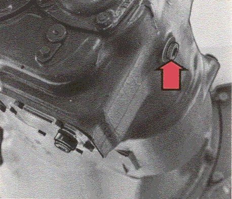
The oil level should be checked during all-round lubrication, that is every 5,000 km.
The oil should be level with the filler hole in the gearbox righthand side.
The filters must not be cleaned. The only servicing requirement which can occur is replacement.
TOC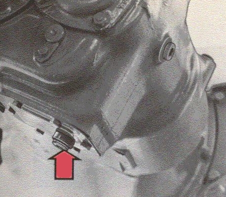
Change the gearbox oil every 20,000 km for buses in city or suburban traffic and every 40,000 km for buses in other traffic.
During running-in the oil should be changed after 10,000 km.
The oil is drained by removing the plug from the drain hole. Drain after driving while the oil is warm as it flows more easily then. Top-up via the level/filler hole.
Oil capacity: approx. 8 litres.
TOCOil according to API-GL-4 must always be used for lubricating the gearbox.
Select the viscosity according to the following table:
| Viscosity1 | ||
| Below -10°C (14°F) |
-10°C to +30°C (14°F to +86°F) |
Above +30°C (86°F) |
| SAE 80 W/903 | SAE 902 or SAE 80 W/902 |
SAE 140 or SAE 85 W/140 |
| 1) | The temperatures refer to stable ambient temperatures. |
| 2) | With very hard driving or lengthy driving at high altitudes (2,000 metres above sea level). SAE 140 or SAE 85 W/140 is recommended instead of SAE 90 or SAE 80 W/90. |
| 3) | SAE 75 W is recommended at very low temperatures. |
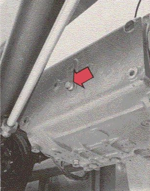
Level plug
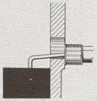
Angle dipstick
Check the oil level every 5,000 km. To check unscrew the level plug and wipe the dipstick with a clean piece of cloth. Insert dipstick as shown in figure. If it remains dry, the oil must be topped up to the angle dipstick.
TOC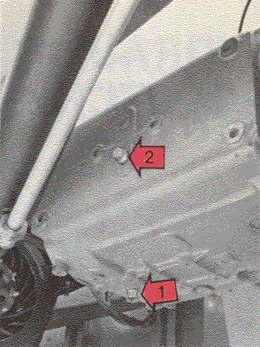
| 1 | Draining |
| 2 | Level/Filling |
Change the oil every 40,000 km or at least once a year. During the running-in, however, change the oil after the first 10,000 km.
Drain the oil immediately after running since it flows easily then.
Fill with new oil until it has reached correct level.
Oil change quantity: ZF S6-80 13 litres
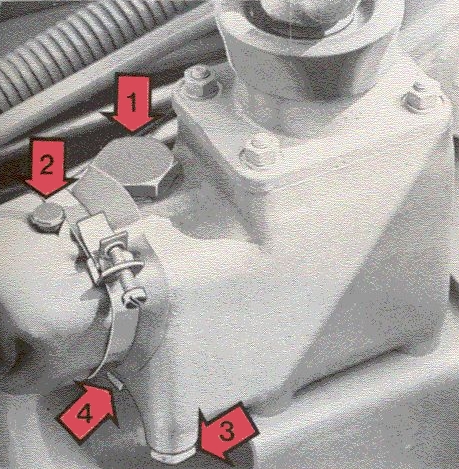
| 1 | Filler hole |
| 2 | Lubricator |
| 3 | Level hole |
| 4 | Drain hole |
Check the oil level connection with the all-round lubrication, that is, every 5,000 km (3,000 miles). If necessary add new oil until it runs out through the level hole. Change the oil every 80,000 km or once a year. Use gear oil SAE 90.
Oil capacity: Approx. 0.5 litres (1 pint).
TOCUse all the year round ATF-oil, type Dexron Il for the hydraulic clutch.
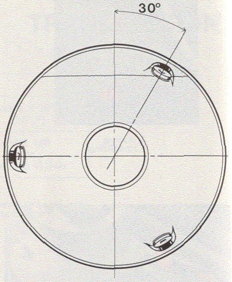
Level/Filler plug
Check the oil level at each all-round lubrication, that is, every 5,000 km. The oil should be level with one of the plugs when it is approx. 30° from the top position. Check that the washer is in good condition before re-fitting the plug.
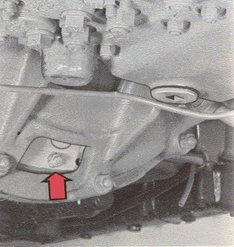
Drain plug
Change the oil every 40,000 km. Drain the old oil by removing one of the plugs in its bottom position. To fill with oil, turn the holes up to 30° from the top position and fill level with the hole.
Oil capacity: approx. 16.5 dm (litres).
TOCThe torque multiplier has the same oil system as the engine. See, therefore, the oil recommendations for the engine.
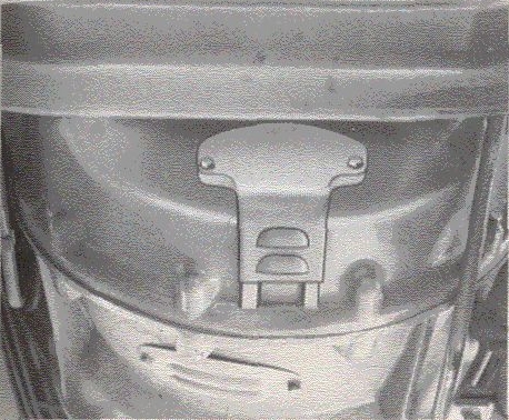
Protective cover
The same oil system is used for the torque multiplier and the engine. So the oil level in the torque multiplier is checked with the warning light for low oil level, see "Before starting" Page 23.
The oil level for the engine and the torque multiplier can also be checked with the dipstick in the oil tank. in this case the engine must be run warm before checking.
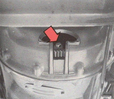
Inspection hole/drain hole
The oil is changed when changing the engine oil, that is, every 10,000 km (6,000 miles). This is done as follows.
Run the engine warm. Stop it by pulling out the mechanical stop control at the oil tank and allow the stop control to remain out. Remove the protective cover and turn over the engine with a screwdriver until one of the two drain plugs on the torque converter is opposite the flywheel casing inspection hole. Unscrew the torque converter drain plug and the drain plugs on the engine.
Fill the engine oil tank with oil. Oil capacity for engine and torque multiplier: approx. 43 litres (9.5 Imp. gals. = 11.4 US gals.).
TOC| Below +30°C | Above +30°C |
| ATF-oil type Dexron II | Engine oil SAE 30 Quality: API SD/CD |
| or Engine oil SAE 20 W/20 or SAE 10 W Quality: API SD/CD |
or Gearbox oil SAE 80 W/90 Quality: API GL 1 |
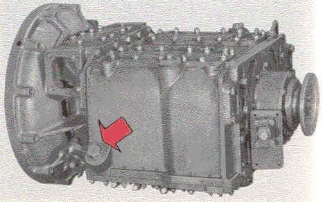
Level/Filler plug
Check the oil level at each all-round lubrication, that is, every 5,000 km. The level is checked at the level plug on the left-hand side of the transmission.
TOC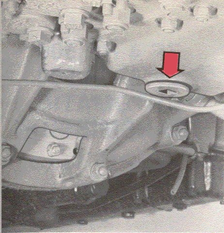
Drain plug
The oil should be changed every 20,000 km. During the running-in, however, the oil should also be changed after 2,500 km. Drain the oil after driving while it is still warm. Topping-up is through the filler hole on the right-hand side of the transmission or through the level hole on the left-hand side. Fill up the lower thread in the level hole.
Oil capacity: approx. 9 dm3(litres).
Clean the oil filter insert when changing the oil in the transmission.
(Also during the running-in after 2,500 km.)
The oil filter is built into the right-hand side of the transmission near the front.
Unscrew the bolts securing the oil filter bottom plate and then remove the filter complete. Unscrew the oil filter centre bolt and disassemble the filter. Clean the parts in white spirit and change the seal. Make sure that the seal tightens properly against the transmission when re-fitting the filter.
TOCThe function of the transmission is dependent on having clean oil of the correct type at the correct level. Very often a malfunctioning transmission is because of dirt in the oil. Always clean, therefore, the dipstick and the oil filler stud when checking or topping-up.
| Oil type: | Engine oil SAE 10 W. |
| Oil quality: | API Service CC, CD, SC, SD or SE (MIL-L-2104 C). |
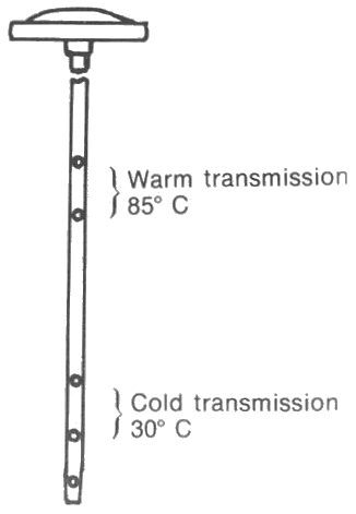
Check the oil level every 5,000 km with the dipstick. This is placed in the oil filler tube.
The dipstick has different marks for a warm and a cold transmission.
With a cold transmission, the oil level check can only be provisional. The transmission should have reached its normal operating temperature in order to get an accurate level. If the bus has not been driven for a long time, i.e. more than 12 hours, the oil level, before warming-up, is higher than normal. This is because oil from the torque converter and oil cooler has flooded into the gearbox and increased level.
Run the bus until the transmission has reached its normal operating temperature, that is, approx. 85° C. Stop the bus, apply the parking brake and allow the engine to idle, selector lever in N.
Wipe the dipstick dry and measure the level in the usual way with the engine running. It should be between the two upper marks on the dipstick. If it is below the lower mark for a warm transmission, top-up. This is done through the oil filler tube.
TOCChange the oil and filter every 30,000 km. During the running-in, however, after the 2,500 km.
Drain the oil by removing the drain plug on the sump and immediately after driving since it can still flow easily.
When filling, fill slowly with approx. 12 dm3 (litres). If it is not possible to fill with all the oil at once, start and run the engine at idle and top-up. Then check the oil level in the usual way.
Oil change quantity: approx. 15 dm3 (litres).
TOCThe function of the transmission is dependent on having clean oil of the correct type at the correct level. Very often a malfunctioning transmission is because of dirt in the oil. Always clean, therefore, the oil filler tube before removing the dipstick to check the oil level. Make sure no dirt gets onto the dipstick.
Oil type: ATF-oil, type Dexron II.
The oil level should be checked at each all-round lubrication, that is, every 5,000 km (or more frequently if operating conditions motivate this).
The level is checked with the dipstick in the filler cover.
Check as follows:
| 1 | Drive the bus until the transmission has reached its normal operating temperature. The oil must be warm to make a proper check of the level. |
| 2 | Stop the bus on flat ground, apply the parking brake and allow the engine to idle. |
| 3 | Slowly move the selector lever through all the gear-changing positions. Stop for a second or two at each position. |
| 4 | Move the selector lever to N (engine idling). |
| 5 | Wipe the dipstick with a clean rag which does not leave fluff, etc., on the dipstick
and check the level in the usual way. The level should be between the marks on the dipstick. If it is below the lower mark, top-up with ATE-oil type Dexron II. If the level is above the upper mark, drain some of the oil to get below this level. |
Change the oil and oil filter every 40,000 km or at least once a year.
During the running-in, however, change the oil and oil filter at the 10,000 km warranty service.
(For a newly overhauled transmission, the oil and oil filter must be changed for the first time after 1,000 km.)
Oil change quantity:
approx. 13 dm3 (litres). for MT 643/644
approx. 14 dm3 (litres) for MT 654 CR
| Viscosity | ||
| Below -10°C | Between -10°C and +30°C | Above +30°C |
| SAE 80 W/90 or SAE 80 W/140 |
SAE 90 or SAE 80 W/90* |
SAE 140 or SAE 85 W/140 |
*) With very arduous driving or lengthy driving at altitudes of more than 2,000 metres above sea level, SAE 140 or SAE 85 W/140 is recommended instead of SAE 90 or SAE 80 W/90.
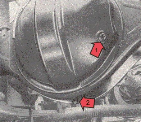
| 1 | Level/filler plug |
| 2 | Drain plug |
The oil level should be checked at each all-round lubrication, that is, every 5,000 km. To check. unscrew the combined level/filler plug. The oil should be level with the hole.
If topping-up is required, use the same type of oil already in the final drive.
NOTE! Also check the rear axle ventilation. It is important that it is not blocked otherwise this will cause overpressure in the rear axle and result in oil leakage.
Change the final drive oil every 40,000 km.
Change it, however, at least once a year even if you drive less than 40,000 km in that year.
During the running-in you' must also change as follows:
| 1st time = | at 10,000 km warranty service, when the final drive is flushed through with the same type of oil to be subsequently used in the final drive. |
| 2nd time = | 40,000 km. |
Drain the oil immediately after driving since it flows easily then.
Drain by removing the bottom plug in the rear axle casing.
| Oil capacity: |
| EV80, single-speed, approx. 9.5 dm3 (litres) |
| EV85, single-speed, approx. 12 dm3 (litres) |
| TS80, two-speed, approx. 9.5 dm3 (litres) |
| TS85, two-speed, approx. 9.5 dm3 (litres) |
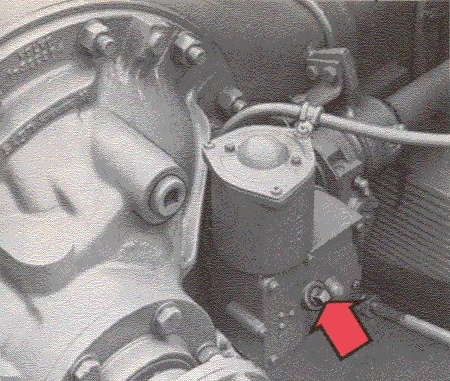
Use SAE 10 W engine oil for lubricating the two-speed final drive control housing. At very low ambient temperatures (below -15°C), the lubricant must consist of 1 part paraffin and 3 parts engine oil SAE 10 W.
Check the oil level in the control housing for the two-speed final drive every 10,000 km.
The oil should be level with the plug hole.
TOCUse ATF-oil type Dexron II for the power-assisted steering system.
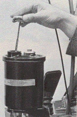 21 Checking the oil level
The oil reservoir is situated at the very front on the right side of the bus. Check the oil level with the dipstick which is fixed in the reservoir cover.
Check the oil level every 5.000 km. The engine must be switched off. The level should be at the MAX. mark. If it is lower than this, top-up with the engine switched off to eliminate risk of air being sucked into the engine.
Oil and filter must be changed at the 10,000 km warranty service. The oil should then only be changed in connection with work on the power-assisted steering system.
The filter must be replaced every 80,000 km or at least once a year.
Clean the outside of the holder. Remove the old filter insert. Hold a finger under the centre hole to prevent any dirt, etc., from the inside of the filter from getting into the holder. Oil the filter sealing ring and re-fit the new insert.
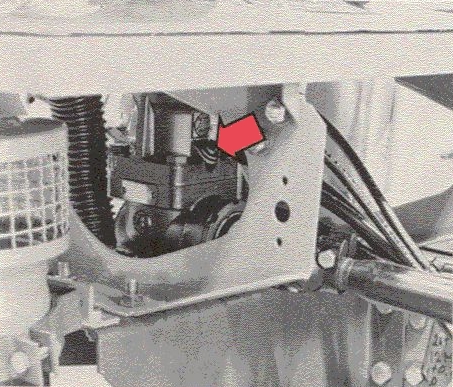 23 Checking the angle gear, steering gear oil level (only LHD)
The angle gear is situated at the bottom of the steering column. Check the oil level at each all-round lubrication, that is, every 5,000 km. It should be level with the plug.
Oil: ATF-oil type Dexron II.
TOC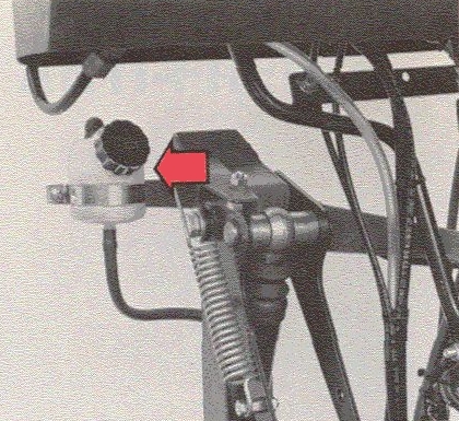 24 Checking the clutch fluid level
Check the level every 5,000 km. The level should be half way up the reservoir.
Use brake fluid which meets the requirements according to the standard SAE J 1703 (DOT 3 or 4).
ATF-Oil type A or Dexron II.
Check the oil level at every all-round lubrication, that is, every 5,000 km.
Oil: ATF-oil, Type A or Dexron II.
The filter should be changed every 40,000 km. During the running-in also after the first 2,500 km. Change the oil every 80,000 km.
Oil capacity: approx. 12 dm3 (litres).
The lubrication points in the chassis can be seen from the lubricating chart at the end of this manual.
TOC| Cooling system |
| Fuel system |
| Electrical system |
| Tyre pressure |
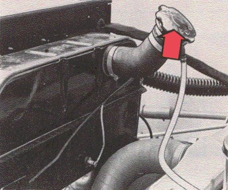 28 Checking the coolant level
Check the engine coolant level daily when starting the engine.
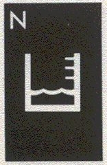
The coolant level is checked with the indicator lamp for low coolant level.
It can also be checked on the expansion tank.
If topping-up is necessary, make sure that the mixture is similar to that already in the engine. Never fill a hot engine with cold water. The large difference in temperature can crack the engine block.
TOCThe bus is delivered from the factory with the cooling system filled with coolant and anti-freeze (glycol) which provides protection against frost down to -35°C. This mixture can be used for the first year. The coolant should then be changed every autumn. Never use a weaker glycol mixture than 40 % glycol.
The glycol protects the cooling system in the winter against freezing and in the summer from rusting.
The following table shows the glycol requirement for protection against frost at different temperatures.
Use Volvo's glycol.
| Glycol % | 40% | 45% | 55% | 60% |
| Protects against frost down to | -25°C | -30°C | -40°C | -56°C* |
*) -56°C is the maximum amount of frost protection which can be provided. To increase the percentage of glycol above this will only impair the frost protection.
WARNING! Glycol is poisonous.
During the warm part of the year, a rustproofing additive can be added to the coolant on certain markets where the anti-freeze is not necessary. Use Volvo's rustproofing additive for diesel engines. This is contained in containers of 118 grammes which is enough for about 10 litres coolant.
P/N 1128383-5.
Mix the additive in several litres of water and fill the cooling system with the mixture. Run the engine warm as soon as possible after filling the system so that the rustproofing will have maximum possible effect.
TOC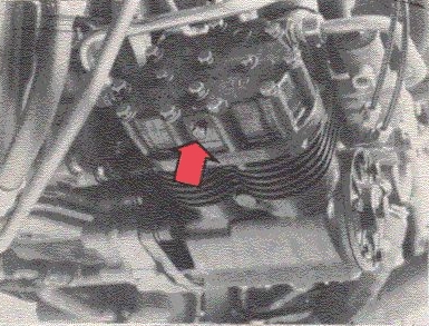
Compressor (plug)
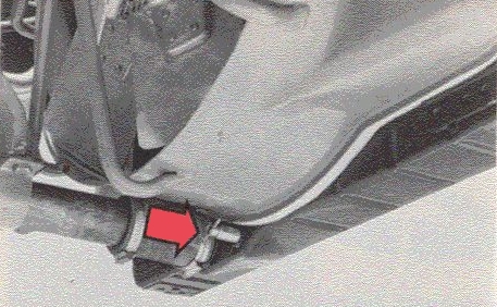
Radiator
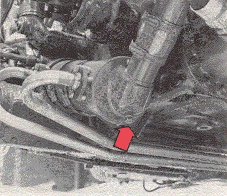
Hose between engine and water pump (plug)
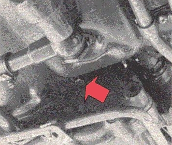
Engine (plug)
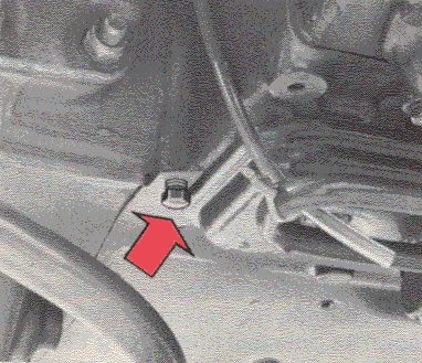
Engine (plug)
All drain points must be opened in order to empty the cooling system entirely. Moreover the expansion tank cap should be removed. There are five drain points for draining the cooling system. One is situated on the compressor, one on the radiator, one on the hose connection between the water pump and engine block and two underneath the engine block. Also drain the heating system.
TOCSwitch off the engine before filling the system with coolant. The coolant level should be checked when the engine has been run warm. Top-up if necessary.
The coolant filter must be replaced in connection with a change of coolant. Over and above this it is recommended that the filter be changed every 20,000 km.
With separate filter replacement, that is, when the coolant is not changed at the same time, close the cock on the filter container before unscrewing and removing the filter.
Smear the rubber seal on the new filter cartridge with a light layer of oil.
Screw on the filter until the seal makes contact with the contact surface and then tighten up the cartridge 1/2 turn by hand. Open the cocks again.
TOCREMEMBER that you must always observe the greatest cleanliness when working with the diesel engine's fuel system. Always use those diesel brands supplied by well-known oil companies. Never use brands of a poor quality.
The special winter fuels supplied by the large oil companies should be used during the wintertime. Because of the lower temperatures that prevail then, the winter fuels are not so sluggish and this reduces the risk of wax deposits in the fuel system. Please observe that we do not recommend that you mix methylated spirit with the diesel oil. Small amounts as little as 1/2% can damage the fuel system. Make sure instead that you have tank well filled and so avoid condensation in the tank.
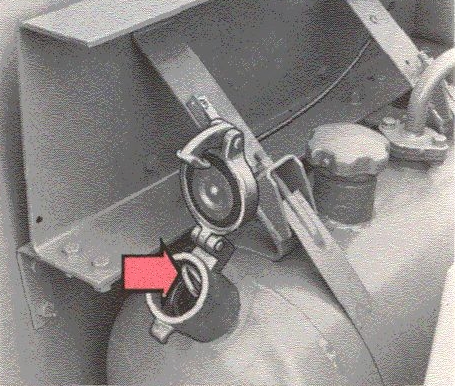
When filling the tank at a petrol station always make sure that the tank cap and round the filler hole are clean. If you fill from your own tank or container, you would be advised to make sure that it is clean and that you filter the fuel.
Concerning fuel specifications, see Page 90.
The anti-tamper seals on the injection pump may only be broken by authorized mechanics. With unauthorized breakage of the seals, the warranty becomes null and void. The injection pump must be anti-tamper sealed in accordance with current regulations.
TOC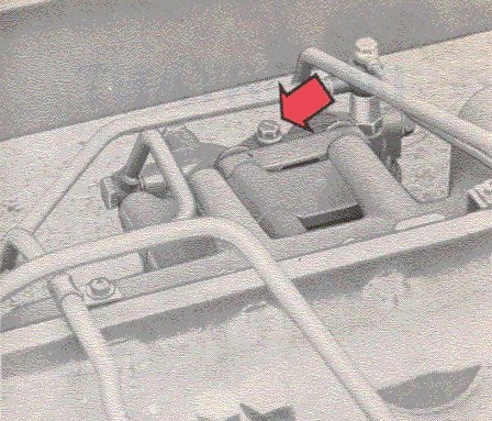
Fuel filter bleed valve
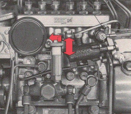
Feed pump
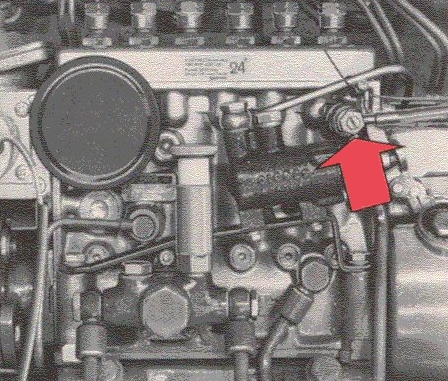
Bleed screw, injection pump
Sooner or later during the lifetime of the bus the fuel system will have to be bled, since this is done when:
Bleeding is as follows:
| 1 | Open the bleed valve on the fuel filters. |
| 2 | Screw up the hand primer and pump fuel into the fuel system with it. When fuel free from air bubbles starts flowing out, close the bleed screw for the fuel filters whilst the fuel is flowing out. |
| 3 | Open the bleed screw on the injection pump. It is provided with a plastic hose to prevent the fuel
flowing out from getting into the engine and causing an unpleasant odour in the bus. Continue priming until
fuel free from air bubbles flows out. Then close the bleed screw whilst the fuel is still flowing out.
Continue priming with a further 10-20 strokes with the bleed screw closed. Turn down the handle on the feed pump. |
| Check for fuel leakage after bleeding the fuel system. |
The bus electrical system is run on 24 volts. Current is supplied by two 12 V batteries and an alternator. The system is a single-pole system and the chassis and the engine block are used as earth conductors.
Note! The following must be observed when doing any work on the electrical system:
| 1 | Make sure that the batteries are connected with the correct polarity A positive cable to a negative pole or a negative cable to a positive pole would ruin the alternator rectifier very rapidly. |
||||||||||||
| 2 | The charging circuit must not be broken while the engine is running The charging circuit goes from B+ on the alternator to the battery positive pole, and from its negative pole to one or earth points on the body. If the circuit or the earth cables are broken or disconnected while the alternator is charging, this will damage the alternator rectifier. |
||||||||||||
| 3 | Rapid charging and starting aid Remember the polarity - positive to positive and negative to negative! Positive to negative would damage the rectifiers very rapidly. We recommend that one of the battery cables is disconnected before rapid charging. When using, on the other hand, jumper cables as an aid in starting, all cables must be connected up. Never use a rapid-action charger as an aid in starting. This would damage the alternator rectifier. |
||||||||||||
| 4 | The following must be observed prior to doing any electrical work on the vehicle: Disconnect: |
||||||||||||
|
Also make sure that any loose cable ends do not touch the vehicle.
If these instructions are followed, there should be no damage to the alternator or regulator when welding. After connecting the cable connections and washing the engine, spray the electrical parts with rustproofing.
Check the electrolyte level each week.
The battery box is situated on the left-hand side of the bus. The electrolyte level should be approx. 10 mm above the cell plates. If the level is too low, top-up with distilled water. Never add too much, since the acid can spill over and cause damage to the paintwork, etc. Check the attachment for the cables when checking the elctrolyte level.
NOTE! Never hold the bulb glass in your hand when changing a bulb. Any grease, oil, etc., on the glass can cause the glass to emit fumes when warm and this can damage the reflector. This applies particularly to the headlight bulbs.
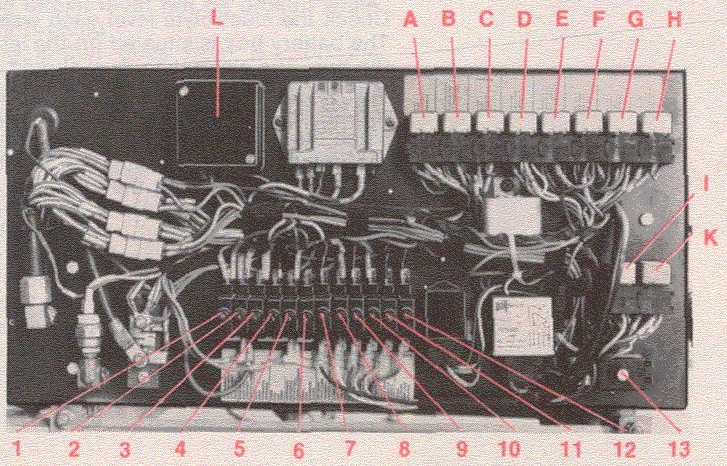
TOCThe fuses and relays are situated in the electrical distribution centre. When the bus is delivered, this centre is placed on the frame and connected to the instrument panel by means of a cable harness.
Its final position will depend on the coach body work, etc.
The fuses are of the automatic type. In other words, they cutout automatically when overloaded. After fault tracing and any repairs, re-set the fuse by pushing in the button. Should the same fuse "blow" repeatedly, obviously something is wrong with the electrical system which should be checked by the proper workshop.
Certain relays are interchangeable. If a relay covering an important function should be damaged you can replace it with a relay which has a less important function. The list below shows which relays are interchangeable.
|
|
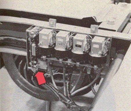
Fuses, electric retarder
Check the function of the pressure regulator and the brake failure warning light when starting the engine. Any faults should be adjusted as soon as possible by an authorized Volvo workshop.
If the pressure drop during the test described below should exceed 5 bars (5.0 kgf/cm2), this points to abnormal leakage and should be put right by an authorized Volvo workshop.
The brake system is provided with an air dryer. This separates moisture from the compressed air and thus prevents valves in the brake system from freezing up.
The moisture is separated in a ceramic filter which must be changed once a year. The separated water drains automatically.
The brake system compressed-air reservoirs (2 double reservoirs) are provided with manual bleed cocks. Look for condensation water in the compressed-air reservoirs to check to see whether the air dryer is functioning or not.
The ceramic filter is adversely affected by alcohol mixtures in compressed air. When charging the buses compressed air system from an external source (can involve the use of alcohol mixtures) the external source must be connected after the air dryer.
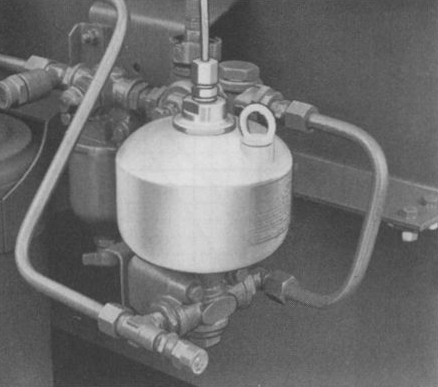
Antifreeze container (early prod.)
As antifreeze, you should use methylated spirit (or corresponding fluid containing at least 95% alcohol). It should be added each autumn and whenever necessary. The container holds one litre (2 pints). The pump operates automatically and the amount of anti-freeze injected can be regulated from 0 to 0.5 cm3 per injection. During the warm season, the injection quantity should naturally be 0, and up to 0.5 cm3 during the colder part of the year.
In the summertime, you should fill the antifreeze container with 1/4 litre (1 pint) engine oil in order to avoid damage from rusting. However, the anti-freeze pump should be emptied first. When engine oil has been filled, depress the brake pedal some 10-15 times. Then set the anti-freeze pump to 0.
When filling with anti-freeze for winter use, it is not necessary to drain the oil, but the injection quantity should be readjusted.
TOCCheck the tyre pressure every week.
NOTE! the air pressures in the diagrams refer to cold tyres. After you have driven several miles the temperature in the tyres will rise and also the air pressure which rises to 0.8-1.9 bar (kgf/cm2) higher than is the case with cold tyres.
With warm tyres, you should alter the air pressure only if the tyres have to be pumped.
The curves are general. The recommendations of the tyre manufacturers should primarily be followed. According to these recommendations, it may be necessary to increase the air pressure by 0.5-1.0 bar (kgf/cm2) for certain types of driving.
 TOC
TOC
Maintain the proper tyre pressure.
Remember that tyre wear increases with speed. Do not drive with imbalanced wheels.
Check the wheel toe-in regularly.
Do not change round the wheels unnecessarily.
With twin-mounted wheels, only tyres of the same type and diameter (max. 6mm difference) should be fitted together.
When about to change a wheel, first slacken the wheel nuts a few turns and then jack up the bus so that the wheel is off the ground. Then remove the wheel nuts completely and lift off the wheel.
Before installing a wheel, clean and lubricate the threads on the wheel studs. Clean the contact surfaces on the wheel and brake drum. When fitting a wheel, tighten up the wheel nuts diametrically and a little at a time until all are well-tightened. Spoke wheels should be tightened up in sequence.
| Tightening torque: | |
| disc wheels | 350-440 Nm (35-44 kgf m). |
| spoke wheels | 300-340 Nm (30-34 kgf m). |
Check-tighten the wheel nuts after the vehicle has been driven a short distance.
| Top | Next |